


㈢ Installation schematic diagram and main components:
1. Installation methods are divided into: vertical type (a) and horizontal type (b) (as shown in the figure below).
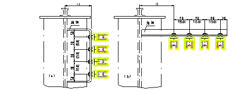 |
2. Device schematic diagram:
1. Terminal cover 2. Bipolar collector 3. Rail joint 4. Suspension seat 5. Rail and sheath 6. Power feeder
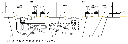 |
3. Joint device:
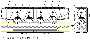 |
3. Joint device:
1. Joint sheath 2. Guide rail 3. Connecting screw 4. Aluminum joint 5. Rail sheath
6. Copper cable lug 7. Power cable
㈣ Power supply methods:
When considering the power supply points of the sliding contact line, the total number and total capacity of electrical equipment on the same span of sliding contact line, the voltage drop value over the full length based on the duty cycle, and the ambient temperature should be considered first (the voltage drop calculation can be based on the data in the previous guide rail parameter table). The following power supply methods are generally available for user reference: ① Single-end power supply; ② Middle power supply; ③ Both ends power supply; ④ Power supply at 1/6 from both ends; ⑤ Power supply at 1/10 from both ends and middle three-point power supply, etc.
Note: The above information and technical parameters are compiled and released by Yangzhou Dary Electric Co., Ltd.