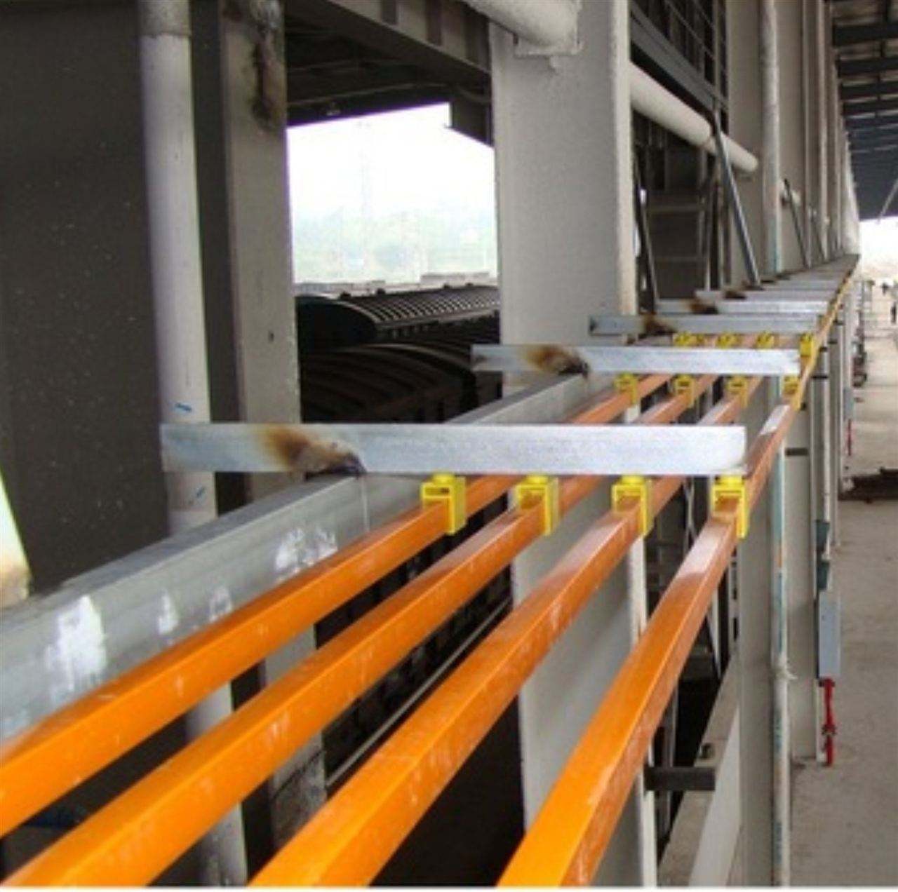
(1) Power supply duct: carries the current from the power source to the current collector. Each duct is 4M long, and can be customized according to customer requirements. See Table 3-1 for specifications.
(2) Current collector: slides in contact with the rail inside the duct to conduct current and provide current to other mobile electrical devices (see Figure 5-1).
(3) Middle inlet box: a device for introducing power current from the middle of the duct (Figure 5-2)
(4) End inlet box: a device for introducing power current from the top end of the duct (Figure 5-3)
(5) Connecting clamp: located at the connection of two adjacent ducts, used for connection, fixation, and insulation (Figure 5-4)
(6) Shaping clamp: keeps the duct from deforming (Figures 5-5, 5-6)
(7) Fork: transmits moving thrust or pull to the current collector, and moderately absorbs transmission errors and shocks. The fork can be matched according to the number and model of current collectors (Figure 5-7)
(8) Outdoor safety busbar trench structure
Multi-pole busbar installation scheme, precautions for product selection
(1) Power supply method
When the voltage drop exceeds the standard, besides selecting a larger cross-section duct, different power supply methods can be used to change the calculated length L.
(2) Determination of thermal expansion compensation
1. Indoor installation: For total length within 100m, generally no thermal expansion compensation point is added. During assembly, leave a gap of 5mm at the duct joints.
(1) Multi-pole busbar installation scheme, gap compensation method:
Principle: Leave staggered gaps between adjacent ducts at the connections for thermal expansion compensation. The ends of the compensation points should be fixedly suspended, and the rest floatingly suspended. The compensation gap for each duct section is as follows: