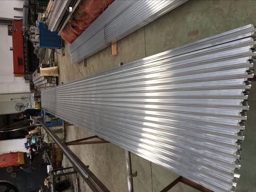
Safe sliding contact wire steel-aluminum composite contact rail consists of a lightweight conductive aluminum rail body and a very wear-resistant stainless steel contact surface. The rail body is extruded from high-strength corrosion-resistant aluminum alloy (6101-T6). The contact surface is a continuous 6mm thick stainless steel strip. The stainless steel strip is mechanically compounded with the conductive aluminum rail to ensure metallic bonding between them, thereby ensuring a small contact resistance between the aluminum and the stainless steel strip. At 20°C, the DC resistance of the composite rail does not exceed 8.5 milliohms per meter. The composite rail is supplied in lengths of 15 meters, and each 3000A contact rail weighs approximately 218kg with a length of 15m. On standard main lines, the contact rail is placed on insulating support devices at calibrated distances of 3 to 5 meters (tolerance for bracket positioning is ±10 mm). Note: In special sections, such as stations, turnouts, curves, slopes, or expansion joints, the distance between insulating support devices should not be less than 3m. The ordinary joint for safe sliding contact wire steel-aluminum composite contact rail is suitable for fixedly connecting adjacent contact rails and conducting current. The connection holes of the composite rail and the fishplate have minimal tolerances, so that when they fit together, only minimal or almost no relative movement is allowed. The joints of the contact rail must be installed flush, ensuring that the side covered with stainless steel strip is installed flush, without any unevenness or twisting, with an installation accuracy of 0.5mm. The expansion joint is designed to accommodate thermal expansion and contraction caused by ambient temperature changes, temperature rise due to current, sunlight, and movement of the composite rail. The expansion joint assembly is required to align with the contact surfaces of adjacent running rails to ensure smooth passage of the train's collector shoe. The safe sliding contact wire expansion joint is 1975 mm long. On straight sections, the expansion joint should be installed as much as possible at the center between two support devices, with a minimum distance of not less than 400mm from each end of the expansion joint to the support device. If expansion joints are installed in curved sections, the insulating supports and expansion joints will be subjected to significant tension. The sliding block of the expansion joint will accelerate wear due to this additional tension, and the insulating supports will also wear out quickly. Therefore, expansion joints are generally not installed at curves. In special cases, where a curve with a radius less than 300m must have an expansion joint, the expansion joint can still function, but the tension for opening and closing the expansion joint will be transferred to the insulating supports. Given the distance between anchor points, this should be taken into consideration. The intermediate joint for electrical connection of safe sliding contact wire, in addition to connecting two independent steel-aluminum composite rails, is also used to introduce external current into the contact rail. Each intermediate joint can connect 8 to 12 cables of 240mm2. The cables must have sufficient slack to avoid applying additional force to the composite rail, thereby hindering its longitudinal movement. The end bends of safe sliding contact wire are divided into two types according to main line and depot line. The main line bend has a length of 5.2m, with a height difference of 126mm between the two ends of the end bend; the depot line bend has a length of 3.4m, with a height difference of 129mm between the two ends of the end bend. The end bend is connected to the contact rail using ordinary joints. Its function is to ensure that when the train runs at rated speed, the collector shoe can smoothly contact and detach from the composite rail
Note: The above information and technical parameters are compiled and released by Yangzhou DARUI Electric Co., Ltd.