Darui Electric recommends
The product rail is formed by cold-rolled steel plate in one cold drawing process to ensure the precision of the rail cross-section dimensions, replacing the unsafe, heavy, and problematic angle steel and other conductive methods that cause short circuits due to dust accumulation on indoor slide lines and ice formation outdoors, affecting usage. It features domestic innovation, with rail unit lengths of 4-6m connected by couplers, extendable to any length as needed.
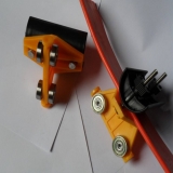
The working principle of this product is shown in the engineering application diagram (1). The starting end of the flat cable (connected to the site junction box) is fixed to the starting end fixer of the guide rail. Then, according to the space allowed for operation on site, appropriate intervals (1-2.5mm) are used to sequentially fix the cable to the four-wheel trolleys carrying the cable. The end of the cable (connected to the power supply) is fixed to the last trolley (towing vehicle). Through the reciprocating movement of the spring-pulled trolley, the cable is dragged (if the length exceeds 20m, a towing rope should be considered to protect the cable from tension), causing all trolleys to slide freely on the rail at any speed. The guide rail is easy to install, requires no debugging, and has the advantages of contactless power supply, making it safe and reliable.
C-3.2 Cable Slide Guide Rail
3. Main technical data of cable slide line:
1. Rated voltage: below AC750V.
2. Material and cross-sectional area of each core wire: rubber-sheathed flat flexible cable, multi-strand copper core wire 1.5-50mm2. 3. Ambient temperature: -20°C~+90°C. 4. Running speed of four-wheel trolley: <90m/min. 5. Working life of four-wheel trolley: <3200h. 6. Maximum allowable static load: 150kg.
4. Ordering information for cable slide line
1. Rail length (m)
Determined by the user based on the actual running distance of the crane, plus the distance for storing the four-wheel trolleys.
2. Cable length (m)
Actual running length + distance for storing trolleys + necessary length to reach the electrical equipment and junction box.
3. Number of four-wheel trolleys
Generally half of the total rail length; users can increase or decrease the number of four-wheel trolleys based on the allowable cable sag space.
4. Number of coupling connectors:
Based on the total rail length; rails exceeding 4m require accessories.
5. Quantity of other accessories:
The quantity is determined by the user based on the number of mobile cranes; generally, each crane requires one set of accessories, each set includes:
1. Rail stopper: 1 piece
2. Rail starting end cable fixing piece: 1 piece
3. Towing frame (towing vehicle): 1 piece
Ordering information
1. Rail length (m)
Determined by the user based on the actual running distance of the crane, plus the distance for storing the four-wheel trolleys.
2. Cable length (m)
Actual running length + distance for storing trolleys + necessary length to reach the electrical equipment and junction box.
3. Number of four-wheel trolleys
Generally half of the total rail length; users can increase or decrease the number of four-wheel trolleys based on the allowable cable sag space.
4. Number of coupling connectors