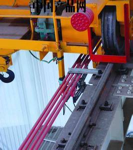
The JDC type safe busbar (also known as H type) uses an aluminum alloy with an H-shaped cross-section as the current-carrying conductor. It transmits electrical energy to the electrical equipment through the sliding contact between the carbon brush of the collector installed on the moving equipment and the current-carrying body.
Product Features
JDC busbar The current-carrying conductor is made of aluminum profile, which has high strength; the good containment, insulation, and resistance to heat and cold of the plastic trough shell make it very safe. Each phase is laid separately, with good inter-phase insulation, enabling large-capacity power supply; the sliding contact surface of the profile is embedded with stainless steel wear-resistant material, greatly extending the service life of the busbar; the standard length is 6m, and it can be installed outdoors or on the same side as the crane cab, making installation and maintenance quite convenient
Main Components
1. Busbar: It is the main component for power transmission. The shell is a plastic insulating trough, with an H-shaped cross-section current-carrying body (called the guide rail) embedded inside, and the contact surface with the carbon brush is made of stainless steel wear-resistant material. The standard length is 6m, with a minimum allowable bending radius (horizontal bending) of R>1.5 meters, and it can be installed upright (as shown in Figures 4.2 and 4.3) or side-mounted.
2. Hanger: A device for installing the busbar on the support frame. Before installing the busbar, pre-thread the required number onto the busbar according to needs, with the hanging bolts on the opposite side of the busbar slot. The installation spacing for 100A-400A is 1.5 meters, and for 500A-1200A it is 3 meters. During installation, first tighten the hanging nuts by hand, and after adjusting the distance between the busbar and the crane track and the spacing between each line, tighten them firmly.
3. Connector: Used for connecting each section of the busbar supplied in fixed lengths. During installation, place a plastic protective cover on each end of the fixed-length busbar, and install an aluminum alloy connector head on one end. When installing the aluminum alloy connector head, note that only 1/2 of the aluminum guide rail should be inserted into the aluminum connector, leaving the remaining 1/2 for the other guide rail to insert. After adjusting the connector position, tighten the connector nut and cover it with the joint protective cover.
4. Power supply connector: It is the component that supplies power to the busbar. It is the same device as the guide rail connector. When power supply is needed, drill a hole in the round end cap of the protective cover to lead in the wire. Press the wire lug under the connector nut. According to circuit requirements, single-point or multi-point power supply can be used.
5. Expansion joint: A special section added to compensate for thermal expansion and contraction when the temperature difference is large and the busbar is long (not considered within 200M). Its installation method is the same as the connector.
6. End cap: Used for sealing the ends of the busbar, and can also serve as an end power supply. The installation method is the same as the connector.
7. Current collector: A device that transmits the electrical energy of the busbar to the electrical equipment. It is installed on the electrical equipment. During installation, pay attention to the direction of the mounting square steel of the current collector to avoid twisting, and keep it parallel to the installation plane of each busbar, and keep the rocker arm of the current collector parallel to the busbar installation plane and perpendicular to the busbar direction. For busbars with curves, use special current collectors.
Note: The above information and technical parameters are compiled and released by Yangzhou Darui Electric Co., Ltd.