Daru Electric recommends
Sliding contact lines come in various structural forms, but the general principle is as follows: Since mobile equipment needs to constantly change positions, at each different position, the equipment must be able to obtain power at any time, otherwise it cannot continue moving. This is where sliding contact lines come into play. We lay several conductors parallel along the track of the mobile equipment and connect them to the power supply. On the moving equipment, we install current collectors that can draw power from the conductors. Thus, when the equipment moves, the current collectors move synchronously with the equipment, continuously drawing power from the conductors to supply the equipment, allowing it to keep moving. The device composed of these conductors and current collectors is called a sliding contact line.synchronously, and obtain power from the conductors at any time to provide it to the equipment, so that the equipment can continue moving. The device composed of these conductors and current collectors is called a sliding contact line.
Depending on the electrical equipment, sliding contact lines come in various forms. For example, in subways, the steel rails on the side of the tunnel are used as sliding contact lines, and in industrial and mining enterprises, bridge cranes use three angle steels as three-phase sliding contact lines.
Sliding contact lines are mainly used in various lifting and transport machinery, production lines, and other facilities and places that require mobile power supply, such as cranes, loading bridges, electric hoists, three-dimensional warehouses, amusement equipment, air conditioning testing lines, etc. They are widely applied in many industries including lifting and transport, electric power, shipbuilding,ports, metallurgy, mining, water plants, environmental protection, chemical industry, home appliances, automobiles, clothing, tobacco and alcohol, amusement, and many other industries.
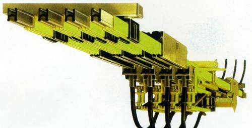
Safety sliding contact line is a new type of mobile power supply device. With its superior properties of insulation, safety, temperature resistance, vibration resistance, and energy saving, it has gradually replaced the old exposed angle iron and copper bar sliding contact lines. The safety sliding contact line consists of smooth and flat T2 copper bars or aluminum profiles embedded with wear-resistant conductors, which are filled inengineeringplastictubes or channel plates, combined to form a power transmission duct. The duct has an opening slot at the bottom to allow the current collector to run, and the high-wear-resistant copper-based graphite brush of the current collector directs the power to the working equipment. The use of safety sliding contact lines brings safety to the workshop, but there are also disadvantages. Bridge cranes are prone to power failure during use, sometimes sparks are generated inside the power transmission duct, and in severe cases, the sliding contact line may "explode", causing frequent replacement of current collectors and affecting production. To address this, the following improvements have been made: (1) Increase the chamfer of the current collector brush and polish it smooth; (2) Increase the spring strength and elasticity between two opposite brushes of the current collector to ensure the springrecoversfreely; (3) Deepen and reinforce the spring seat in the current collector to ensure that the recovery spring of the brush does not easily "displace" during work; (4) The connecting blocks at the joints of two sections of the safety sliding contact line should have chamfers to ensure smooth transition of the current collector. At the same time, to ensure the normal use of the safety sliding contact line, standardized operation by crane operators, regular maintenance by maintenance workers, and regular inspections are also essential.
Note: The above information and technical parameters are compiled and released by Yangzhou Darui Electric Co., Ltd.