Single-pole Busbar Installation Plan
Recommended by Darui Electric
When considering the power supply points for safe busbar, the total number and total capacity of electrical equipment on the same span, the voltage drop over the full length based on the duty cycle, and the environment should be taken into account (voltage drop can be calculated using the data from the previous rail parameter table). The following power supply options are generally available for user reference:①Single-end power supply;②Middle power supply;③Two-end power supply;④Power supply at 1/6 from both ends;⑤Power supply at 1/10 from both ends and at the middle (three-point power supply), etc.
Installation Instructions
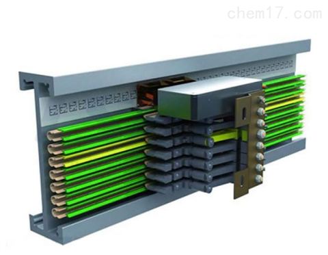
Before installing the busbar, first fix the angle steel brackets according to the installation form selected by the user and the suspension spacing of the busbar. At the installation site, slide the required suspension seats and one joint cover onto each 6-meter busbar section, and install one aluminum connector at one end. When installing the aluminum connector, note that only 1/2 of the aluminum rail should be inserted into the connector, leaving the other half for connecting the next rail. After these preparations, hang the busbar sections one by one on the brackets and connect them along the entire line, tightening the screws on each joint. If the total length of the busbar exceeds 200 meters, expansion devices should be added (expansion devices are available from our factory at any time). When connecting the power supply lines, they can be connected at the joints of each 6-meter section; refer to the previous joint device diagram for the specific connection method.
When installing curved busbar sections, the suspension distance should be shortened accordingly; the specific dimensions can be determined based on site conditions.
When installing the current collector, first mount it on the matching square tube, then fix it to the electrical equipment at an appropriate position that aligns with the busbar. Note that for good tracking performance and good contact between the current collector and the busbar, they should be installed in the same vertical and horizontal direction.
Maintenance
The safe busbar should be inspected regularly during normal operation, because electrical equipment is the main production tool in every industrial and mining enterprise, and any slight error can directly affect the production efficiency of the factory. When inspecting the busbar, check whether the joints at each 6-meter section are loose or disconnected. When inspecting the current collector, check whether the moving parts rotate flexibly, whether the tension springs are fatigued, and the wear of the carbon brushes (these conditions can affect the conductive performance of the busbar and the tracking performance of the current collector; adjustments should be made promptly).
During holiday equipment overhauls, remove the current collector from the guide rail and check the wear of the carbon brush rollers. If the brush protrusion is less than the specified effective length, replace it promptly. If the guide rollers are severely deformed, they also need to be replaced to maintain normal operation of the current collector and good contact of the carbon brushes, and to identify the cause. Among all components of the safe busbar, the carbon brush is the part that normally wears out.
Note: The above information and technical parameters are compiled and released by Yangzhou Darui Electric Co., Ltd.